
Choosing the right superhard tool for high-purity copper depends on the operation, surface-finish target, part geometry, and production conditions. This guide explains how to evaluate PCD cutting tools and diamond grinding wheels for semiconductor copper components.
Copper is used in electrical and thermal applications because of its high electrical and thermal conductivity. Semiconductor-related components may include copper contacts, heat-dissipation parts, lead-frame features, and precision components used in manufacturing equipment.
However, copper’s properties also make it challenging to machine. Depending on the copper grade, temper, geometry, and cutting conditions, the material can deform at the cutting edge, adhere to a tool, form burrs, or produce an inconsistent surface. These effects can complicate dimensional control and finishing.
Surface quality is not determined by tool material alone. Cutting speed, feed rate, depth of cut, edge geometry, machine condition, and workholding can all affect the result. Tool selection should therefore begin with the operation and required part quality, rather than with a grit size or tool material in isolation.
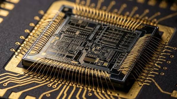
High-purity copper is valued for its electrical and thermal conductivity, but its softness and ductility can make precision machining challenging. Depending on the material condition and cutting setup, copper may adhere to the cutting edge, form burrs, or produce a surface that varies from pass to pass.
PCD (polycrystalline diamond) tools are a strong candidate for precision machining of copper because they combine diamond’s hardness and wear resistance with a cutting edge that can be manufactured for specific operations. They are commonly used for non-ferrous materials, including copper and copper alloys.
For high-purity copper machining, a properly specified PCD tool can offer several practical advantages:
Tool wear can gradually change the effective cutting edge and affect dimensions or surface finish. PCD’s wear resistance makes it a candidate for applications where edge stability and repeatability matter. The actual tool life depends on the copper grade, tool geometry, machine rigidity, cutting conditions, and maintenance practices, so it should be confirmed in the customer’s process.
A sharp, application-specific PCD edge can support fine cutting and help reduce edge-related surface defects. Surface quality is also affected by feed, speed, tool runout, workholding, vibration, and material condition. PCD can contribute to the result, but the finished Ra value must be verified on the actual part and measurement setup.
Where a PCD tool maintains its cutting performance for longer than the current tool option, it may reduce tool-change frequency and related production interruptions. This is most relevant in repeat production, where tool life and consistency can be measured across multiple parts or batches.
PCD tools can be made for operations such as turning, milling, grooving, and profiling. The tool’s rake angle, edge preparation, nose radius, chip space, and dimensions can be tailored to the part geometry and machining strategy. Custom design is particularly useful when standard tools do not provide the required access, chip control, or edge profile.
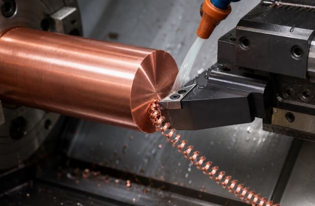
PCD is worth evaluating when the application has one or more of these requirements:
* Tight dimensional tolerances or a demanding surface-finish target
* Repeated production where tool consistency matters
* Frequent tool changes with the current cutting tool
* Difficult chip control or edge-related surface defects
A need for custom tool geometry to reach specific features
PCD is not automatically the best choice for every copper operation. For a low-volume part, a less expensive tool may meet the requirement. If the process includes heavy impact or interrupted cuts, the tool design and PCD grade need careful evaluation. Compare candidates using the same workpiece material, machine, and acceptance criteria.
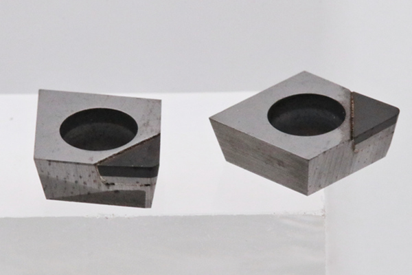
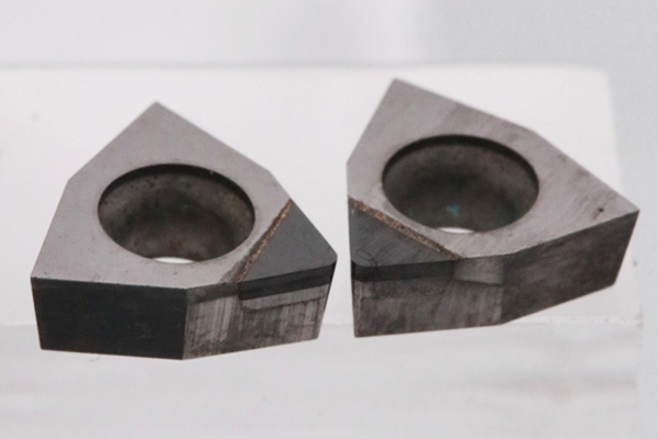
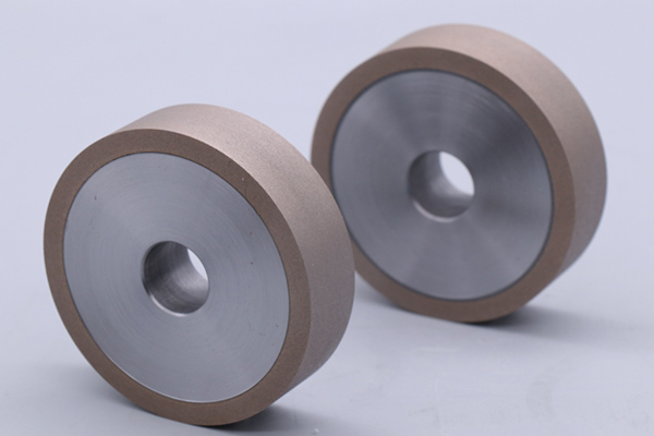
Diamond grinding wheels may be considered when the part requires a grinding or finishing operation, or when the process route calls for controlled stock removal after cutting. Wheel selection should reflect the material, required finish, removal rate, contact area, machine, coolant delivery, and dressing method.
Abrasive size influences the balance between stock removal and finish. A staged process can be evaluated when a single wheel cannot efficiently achieve both objectives: use a suitable wheel for the earlier stock-removal step, then a finer wheel for finishing.
Specific grit sequences should be treated as trial candidates, not universal prescriptions. The right range depends on the wheel specification, machine, copper condition, and finish measurement. Establish the process with sample grinding and measured results.
Resin, vitrified, and metal bonds differ in wheel behavior, including how the abrasive is held and exposed, how the wheel maintains its shape, and how it responds to dressing. Selection should be based on the grinding operation and production priorities, rather than assuming one bond is always best for copper.
The wheel supplier should know the workpiece material, grinding mode, machine, coolant, finish target, and whether form retention or finishing behavior is the main priority.
If copper adheres to the wheel or the wheel’s cutting behavior changes during production, review the wheel specification and the dressing and coolant conditions. Dressing requirements are specific to the wheel bond and machine setup. Ask the wheel supplier to recommend an appropriate dressing approach and verify it during a controlled trial.
Do not assume that a wheel specification intended for a different semiconductor material will transfer directly to copper parts. The workpiece material and grinding application must be considered together.
Semiconductor Industry Solutions
PCD & PCBN Tools Grinding Industry
Diamond Cutting Bruting Polishing
Add: No.171 Zhongyuan Rd, Zhongyuan District, Zhengzhou, 450001, Henan, China
Tel: +86-371-86545906
Phone / Whats App: +86 18339903057
E-mail: [email protected]